

A prefabricated power pod puts the entire critical power chain - transformer, incoming panels, modular UPS, switchgear, compensation, bypass and monitoring - into one factory-built module, in four standard capacities from 1,250 to 2,500 kVA. The site work shrinks to positioning the module and closing standardized busbar connections. This guide walks through what is inside, how it compares with conventional distributed power rooms, and how to configure one for your redundancy target.
In a conventionally built power room, the chain from utility to IT load crosses seven separately purchased, separately commissioned devices: MV switchgear, transformer, LV input panel, UPS, output panel, distribution panel - each with its own supplier, its own interface and its own commissioning date. As rack densities climb, that fragmentation shows up as footprint, schedule slip and fault diagnosis that depends on whoever happened to install the equipment.
The prefabricated pod approach collapses that chain. One manufacturer engineers the whole train, assembles it on a common line, connects everything with copper busbar instead of field cable, tests the complete system at the works, and ships it as one module. On the simplified path, power flows utility to MV switchgear, into the integrated power module, out through busway to the IT cabinets - three interfaces instead of seven.
In our product line this is the ZhiTing Integrated Power Module; the same hardware appears across the industry as power pods, power skids or e-houses. The words differ, the buying decision does not: you are choosing between one responsible factory and a coordination project.
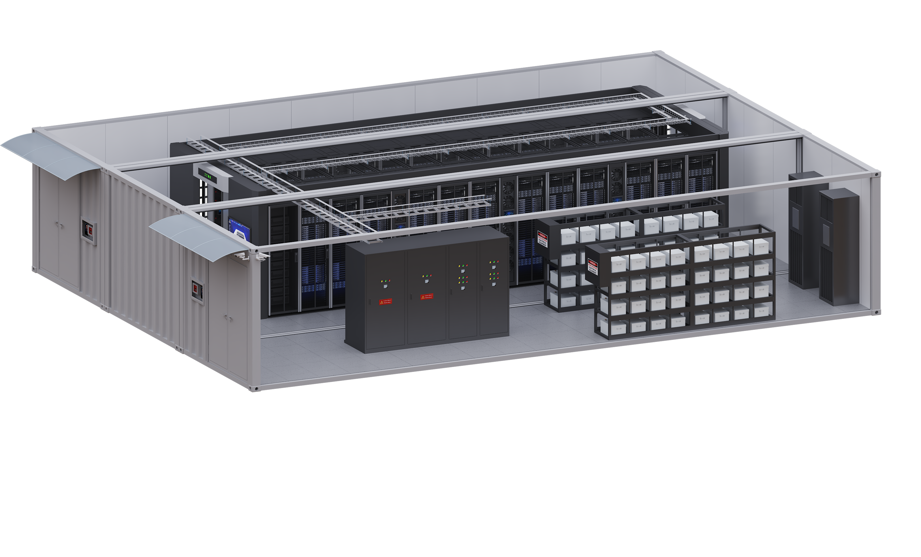
Eight subsystems, engineered and wired as one train:
The frames are fixed-partition or withdrawable low-voltage cabinets, 2,500 mm high and 1,000 mm deep, width configured to the train. Cooling is forced air, front intake and rear exhaust, rated for -5 to +40 degrees C operation.
| Category | Integrated power module | Conventional distributed |
| System architecture | Unified, integrated design | Multiple independently designed systems |
| Supplier management | Single interface, coordinated delivery | Multiple suppliers and work packages |
| Production method | Factory prefabrication and pre-commissioning | Site assembly and commissioning |
| Site activities | Module connection and final integration | Extensive cabling and installation |
| Quality control | Standardized factory testing | Dependent on site conditions |
| Expansion | Modular and configurable | Cross-supplier coordination required |
| Operations | Centralized monitoring and analytics | Multiple standalone platforms |
| Project risk | Controlled and predictable | Interface and construction risk |
The last row is the one that decides projects. Every conventional interface - UPS to output panel, panel to distribution board - is a handshake between two vendors' schedules. In the pod, those handshakes happen inside one factory test report.
Two load patterns and five redundancy architectures cover the practical space:
Capacity frames and headline ratings:
| System capacity | 1,250 kVA | 1,600 kVA | 2,000 kVA | 2,500 kVA |
| UPS configuration | 2 x 600 kVA | 4 x 400 kVA | 4 x 500 kVA | 4 x 600 kVA |
| Incoming switch | 2500A/3P + 2500A/4P | 3200A/3P | 4000A/3P | 5000A/3P |
| Bus coupler | - | 3200A/4P | 4000A/4P | 5000A/4P |
| Maintenance bypass | 2000A/3P | 2500A/3P | 3200A/3P | 4000A/3P |
System-level numbers worth knowing before any vendor meeting: input power factor above 0.99, output power factor up to 1.0, and UPS overload behavior of 105% continuous, 125% for 10 minutes, 150% for 1 minute - the same curve logic that governs downstream breaker coordination. The platform complies with IEC 60950-1 and IEC 62040-1/-2/-3 (with AS 62040 equivalents, EN 50991-2 Class A for EMC).
The delivery sequence runs eight steps: consulting, design, manufacturing, factory testing, transportation, installation, commissioning, operation support. The schedule-critical point is what moves off your site: equipment integration, copper busbar connections, internal wiring, primary equipment testing and secondary control verification all finish at the works, before the module ships.
Transport is engineered, not hoped for: where access allows, the system arrives as a complete module; where roads or doorways do not cooperate, it ships in transportable sections and reconnects on site through standardized main busbar and control interfaces. Either way, the site crew is connecting proven sections, not assembling vendor packages - which is where conventional builds quietly spend their contingency.
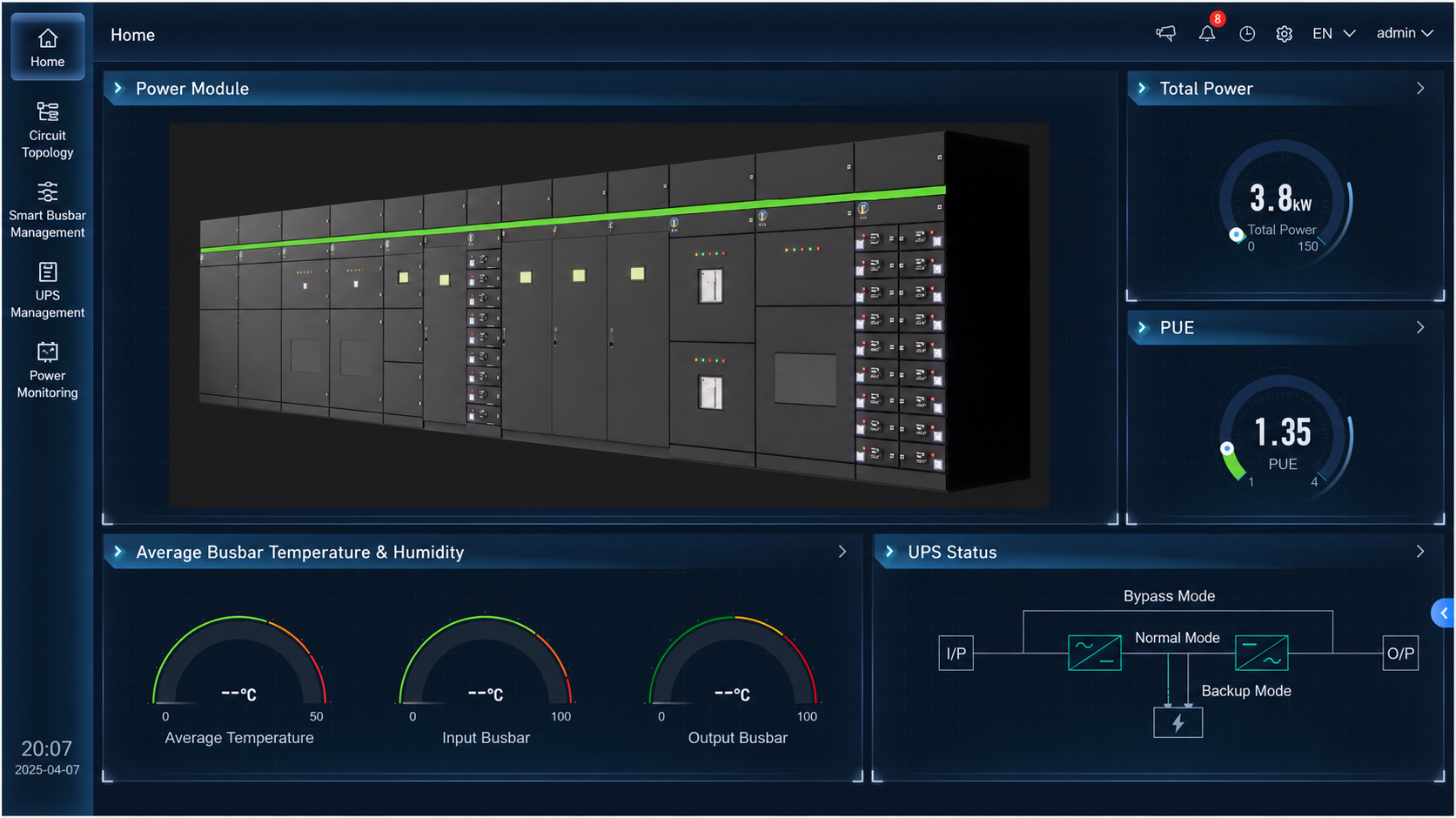
The monitoring platform watches five layers of the train: electrical parameters (voltage, current, power, frequency, power factor, harmonics, energy), equipment status (switch positions, breaker states, UPS health and module condition), environment (temperature, humidity, smoke, access), fault warning (multi-level alarms, trend analysis, condition assessment) and energy management (load profiles, configurable reports). A 15-inch centralized screen sits on the module itself.
Serviceability follows the same logic: modular UPS power modules, bypass modules, monitoring modules and SVG/APF function modules are hot-replaceable, moving maintenance from system-level shutdowns to module-level swaps - and cutting the dependence on specialist site labor that plagues assembled power rooms. At project level, the platform also integrates with photovoltaic generation and battery energy storage where the site energy strategy calls for it.
Buyers mix these up constantly, so the boundary is worth one paragraph. The power pod delivers and protects electricity: transformer in, conditioned and distributed power out to busway. It has no IT white space and no cooling for servers. A containerized data center - like our INFINITY series clusters - wraps power, cooling and IT racks inside ISO containers for full-facility delivery, and internally it uses the same power module architecture. Standalone UPS units (tower, rack-mount, or modular frames from 10 to 600 kVA) are components; the pod is the engineered system around them. If you need power only, specify the pod. If you need the room, specify the container - it will contain a pod's logic anyway.
What is a prefabricated power pod?
A factory-built module containing the complete critical power chain - dry-type transformer, incoming and coupler panels, modular UPS, input/output switchgear, SVG/APF compensation, maintenance bypass, feeder panels and monitoring - delivered pre-tested and connected on site via standardized busbar, in standard capacities from 1,250 to 2,500 kVA.
How much site work does a power pod eliminate?
All primary integration: busbar connections, internal wiring, primary equipment testing and secondary control verification happen at the factory. Site activities reduce to positioning the module or sections, closing standardized busbar and control interfaces, and final commissioning.
Can a power pod support both IT and mechanical loads?
Yes. The IT plus mechanical configuration adds utility power distribution paths for cooling plant, pumps and fans alongside the UPS-protected IT paths - on a single bus, dual bus, A/B dual path, N+1 or 2N architecture.
Author: [Yvonne Sun], Overseas Marketing, Zhejiang Zhiting Information Technology Co., Ltd. - manufacturing data center power infrastructure since 2009: integrated power modules 1,250-2,500 kVA, UPS 10-600 kVA, CE / ISO certified, OEM/ODM supported.
Tell us your needs for data center infrastructure, and our team will provide you with customized green & energy-saving integrated solutions with global delivery and fast response.

 EN