 EN
Containerized vs Modular vs Micro Data Centers
Quick Answer
| Containerized, prefabricated modular, and micro data centers are not three sizes on one product ladder. A containerized data center describes an enclosure and transport format. A prefabricated modular data center describes a delivery and architecture method based on factory-built functional blocks. A micro data center describes a limited local deployment scope, usually close to the workload. One project can fit more than one definition. |
| A buyer should therefore avoid choosing by label. Use this sequence instead: |
- Define the system boundary: state what sits inside the supplied package and what remains at site level.
- Draw every interface: power, cooling, network, controls, fire, structure, drainage, access, and responsibility.
- Choose the expansion unit: another enclosure, another functional block, another local edge node, or a coordinated combination.
- Run an RFP check: make each bidder price the same scope, document exclusions, and prove interfaces through factory and site tests.
| Capacity must be labelled just as carefully as architecture. ZT lists 15–25 kW total IT capacity for a 20-foot container and 40–70 kW total IT capacity for a 40-foot container. These are whole-enclosure values. In the documented 40 kW, eight-rack arrangement, the result is 5 kW per rack—not 40–70 kW per rack. |
The Classification Problem: Three Different Questions
Most comparison charts begin with dimensions, lead time, or cost. That is premature because the three labels answer different questions.
- Containerized asks: what physical package contains the equipment, and how can that package be transported and handled?
- Prefabricated modular asks: how is the facility divided into repeatable factory-built functions, then integrated at the site?
- Micro asks: how much local operational scope is being served as one compact unit?
A “modular data center” RFP may attract an IT container, separate functional modules, or enclosed edge racks, each with different site scope. Use the following definitions on the cover sheet.
| Term | Definition for procurement | What it does not prove |
| Containerized data center | IT or infrastructure packaged in a transportable container-format enclosure, often 20 or 40 feet | Complete site scope, easy future relocation, rack density, or compliance of the deployed facility |
| Prefabricated modular data center | A site assembled from factory-built functional modules with planned physical and controls interfaces | That every module is a freight container, that civil work disappears, or that the facility is mobile |
| Micro-module / micro data center | A compact integrated environment serving a local workload or small failure domain | One universal rack count, kW limit, indoor-only use, or a particular enclosure format |
The categories overlap. A compact container serving one industrial site can be both containerized and micro. A modular campus may combine container-format IT blocks with other functional modules. The label is useful only after the boundary is visible.
The Buyer Workflow at a Glance
Treat architecture selection as a drawing-and-schedule exercise rather than a vocabulary debate.
| Engineering step | Required buyer output | Decision unlocked | Typical failure if skipped |
| 1. Define the system boundary | Scope diagram, rack schedule, load basis, inside/outside list | What is actually being bought | Hidden site work and incomparable bids |
| 2. Draw the interfaces | Interface register with data, duty, owner, and test method | Whether modules can operate as one system | Late cable, pipe, controls, or fire-strategy conflicts |
| 3. Select the expansion unit | Phasing diagram and ultimate-capacity plan | Container, functional block, micro node, or hybrid | Stranded utility capacity or disruptive growth |
| 4. Run the RFP check | Common schedules, evidence list, FAT/SAT matrix, exclusions | Commercially and technically comparable offers | Low headline price followed by variations |
The four steps are sequential. Establish the operating problem before selecting a physical format.
Step 1 — Define the System Boundary
A boundary is the line between the supplier’s integrated package and the rest of the project. Draw it before discussing module count.
Start with the workload. Record initial and ultimate IT load, the expected and peak load of each rack, air- versus liquid-cooled equipment, voltage, feed arrangement, UPS topology, battery autonomy, network paths, allowable downtime, and site design conditions. If the rack schedule is not ready, state that it is provisional and identify who owns the update.
Then mark every function as one of four things:
- inside the supplied unit;
- supplied separately by the same vendor;
- provided by another contractor;
- existing site infrastructure to be verified.
The list should cover racks, UPS, batteries, power distribution, cooling terminals, CDU where applicable, outdoor heat rejection, fire detection and suppression, access control, DCIM, network demarcation, structural supports, weather protection, drainage, lighting, emergency power-off, earthing, and site communications.
Boundary Test A: Containerized
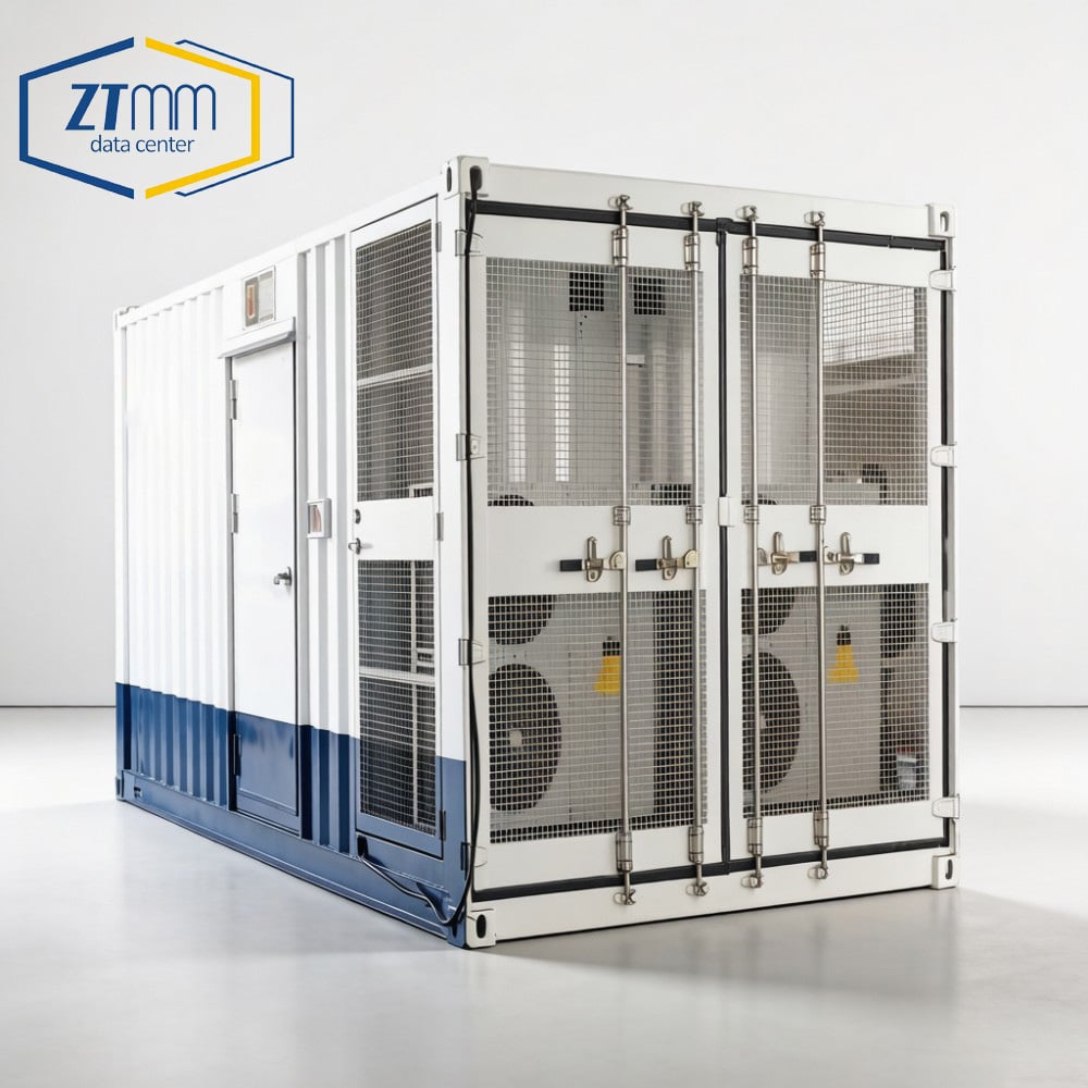
For a containerized data center, the enclosure is an obvious physical boundary, but it is rarely the complete project boundary. Ask what stops at the wall. Does the offered package include only the internal cooling units, or also the external condenser or chiller? Are incoming power cables terminated at an external panel, inside the container, or at site switchgear? Who provides the foundation, stairs, service platform, rainwater management, and protected pipe route?
“Turnkey container” is not an adequate answer. The buyer needs an inside/outside schedule.
Transport requirements also belong inside this boundary definition. ISO 668 sets a framework for Series 1 freight-container classification, dimensions, and ratings, but a modified data center enclosure still needs project-specific review of openings, mass, lifting, structural reinforcement, equipment restraint, route limits, and handling. Transportable at dispatch does not mean relocatable without engineering work after commissioning.
Boundary Test B: Prefabricated Modular
For a prefabricated modular site, define boundaries by function as well as enclosure. An IT module may stop at the busway, chilled-water connection, fire alarm loop, and controls gateway. A power module may include UPS and batteries but depend on separate medium-voltage equipment. Cooling may be supplied as a plant module serving several IT blocks.
This is where modular architecture earns its flexibility: each function can use an appropriate form instead of being forced into one box. It also creates more interfaces. A site-level designer must own protection coordination, hydraulic balance, control sequences, fire zoning, egress, weather seals, and commissioning across module boundaries.
Boundary Test C: Micro
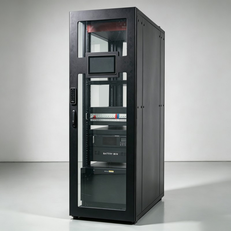
For a micro data center, small physical scope can hide a large operational boundary. The compact unit may be integrated, yet it still depends on local electrical capacity, heat rejection, network availability, room conditions, physical security, remote monitoring, and service access.
The better definition of “micro” is operational, not numerical: a localized workload is managed as one compact environment and one limited failure domain. There is no universal kW or rack-count threshold. Avoid inventing one in the RFP.
Keep Four Power Numbers Separate
Every boundary schedule should give different columns to:
- total IT load of the enclosure or module;
- expected and peak load of each rack;
- cooling-unit duty;
- total site or project capacity.
For ZT’s standard container references, a 20-foot unit is listed at 15–25 kW total IT load, while a 40-foot unit is listed at 40–70 kW total IT load. The documented low-density arrangement is:
|
Whole-container IT load: 40 kW Rack count: 8 Average rack load: 40 ÷ 8 = 5 kW/rack |
An average is not a thermal design. The rack schedule still has to identify the hottest cabinet and any concentrated GPU load. But the arithmetic prevents a whole-container rating from being copied into a per-rack field.
Step 2 — Draw the Interfaces and Assign Owners
Once the boundary is defined, draw the connection points. A simple block diagram is more useful than several pages of “fully integrated” prose.
Each interface needs five entries: location, design condition, providing party, accepting party, and verification method. A pipe connection without temperature, flow, pressure, water-quality basis, valve scope, and controls handshake is not a defined interface. A power connection without voltage, fault level, protection boundary, earthing arrangement, cable scope, and energization sequence is equally incomplete.
Use an interface responsibility table early enough for bidders to challenge it.
| Interface | Minimum information on the RFP | Buyer / site team responsibility | Module supplier responsibility | Acceptance evidence |
| Incoming electrical power | Voltage, frequency, fault basis, feed topology, termination point, earthing | Utility and upstream system, route, declared site conditions | Internal distribution, ratings, termination details, protection data | Approved single-line diagram, inspection, functional test |
| Cooling / heat rejection | Rack heat map, duty points, climate, fluid basis, redundancy, connection location | External plant or ambient path where excluded; site pipe/cable route | Internal cooling train and declared connection conditions | Duty data, leak/pressure tests, alarms, load test |
| Network | Carrier paths, demarcation, diversity, port and protocol needs | Carrier service and external routes | Internal pathways, panels, monitoring connection | Link, failover, and monitoring test |
| Controls / DCIM | Point list, protocol, time source, alarm routing, cybersecurity boundary | Site BMS/NOC integration and access policy | Local controller, gateway, point definitions, sequences | Point-to-point test and cause-and-effect test |
| Fire and life safety | Code basis, zoning, detection, suppression, shutdown and egress logic | Site fire strategy and authority coordination | Equipment and sequence within stated module scope | Approved cause-and-effect matrix and witnessed test |
| Structure / weather | Loads, supports, anchorage, drainage, wind/seismic basis, access clearances | Survey, foundations, site drainage and access where excluded | Module loads, lifting data, anchorage requirements, envelope details | Drawings, calculations, delivery inspection |
| Commissioning | FAT, shipment inspection, SAT, integrated systems test, defect closure | Site readiness, utilities, witnessing, integrated test leadership | Factory tests, records, start-up, module functional evidence | Signed test scripts and issue log |
Responsibility should not be expressed only as “by others.” Name the contractual party. If the civil contractor provides the foundation using loads issued by the module supplier, set dates for preliminary data, approved data, and change control. If a third party supplies the chiller, identify who proves the complete control sequence under changing IT load.
Step 3 — Choose the Expansion Unit
“Scalable” is incomplete unless the RFP names what is repeated and what must already exist.
For a containerized architecture, the expansion unit is often another container or coordinated cluster. Confirm whether upstream switchgear, cooling plant, network capacity, foundations, and controls can accept that block. Also check whether a new unit can be installed without blocking service access or interrupting the first one.
For a prefabricated modular architecture, the expansion unit may be an IT block plus a corresponding share of power and cooling. The modules need not be added one-for-one. A phase could require power capacity before IT capacity, or a cooling plant sized for several later blocks. The master plan should show connection points, isolation, spare controls capacity, egress, lifting routes, and the sequence for live-site work.
For a micro architecture, the usual expansion unit is another local node, not an addition to one central room. That can align investment with branch or production-line demand. It also expands the monitoring estate, spare-parts footprint, and service geography. The ultimate design is therefore an operating model as much as a physical layout.
Density can change the expansion unit. ZT’s engineering references distinguish 5–8 kW/rack for general IT, 15–30 kW/rack for inference or mixed accelerated computing, and 100 kW/rack or higher for AI training using chip-level liquid cooling. At 30–50 kW/rack, rear-door or hybrid air/liquid cooling is reviewed; above 50 kW/rack, chip-level liquid cooling is the practical path in ZT designs. These are design bands, not category definitions.
A future liquid-cooled phase may need a CDU, pipe distribution, water-quality control, leak detection, heat rejection, and residual air cooling that the first air-cooled phase did not require. ZT’s CDU range is 200–1400 kW, with ±1°C secondary-side temperature control and available 1+1 arrangements for pumps, instruments, power, and communications. Do not infer a project CDU quantity from those catalog limits; derive it from the rack schedule, diversity, temperatures, redundancy, and phasing.
Three Short Procurement Scenarios
Scenario 1: Remote Outdoor Capacity With a Defined Load
A buyer needs a bounded IT package at a remote site, with a known rack list and a transport route that can accept the finished enclosure. Containerized is a sensible format to evaluate. The RFP should still separate internal package scope from foundations, upstream power, external heat rejection, communications, lifting, weather interfaces, and recommissioning obligations.
The key decision is not “20-foot or 40-foot” at first. It is whether the declared racks, service clearances, power chain, and cooling arrangement fit the boundary while remaining maintainable.
Scenario 2: A Phased Site With Mixed Density
A buyer expects general-purpose racks in the first phase and denser accelerated-computing zones later. Prefabricated modular is the useful architectural description because IT, power, cooling, and support functions can be planned as coordinated blocks. Some may be container-format; others may not.
The RFP should show the ultimate arrangement now: reserved electrical and hydraulic capacity, isolation points, future module locations, live-site routes, controls addressing, and which shared plant is installed in each phase. Otherwise, “add a module later” can become a disruptive site redesign.
Scenario 3: Local Compute Across Multiple Facilities
A manufacturer or branch network needs small autonomous compute environments close to equipment or users. Micro data centers may fit because the deployment scope is local. The buyer’s main comparison should include remote visibility, physical security, local heat rejection, acoustics where relevant, network loss behavior, standard spares, alarm escalation, and service coverage.
A freight container might be used at one outdoor location, but that does not redefine every micro node as containerized. “Micro” remains a scope decision.
Step 4 — Turn the Architecture Into an RFP Check
The final RFP should make ambiguity expensive for the bidder, not for the buyer after award.
Issue Common Schedules
Provide the same rack schedule, site-condition sheet, responsibility matrix, phasing plan, compliance basis, and test requirements to every bidder. Require assumptions to be returned in marked-up form. A proposal that silently substitutes a lower rack load, different ambient condition, or reduced battery scope is not technically compliant even if its total kW looks correct.
Request Evidence at the Correct Level
A component mark does not certify the deployed facility. Ask for certificate or report identifiers, model applicability, issuing body, validity, and conditions of use. ZT lists ISO 9001, CE, CCC, TUV, RoHS, UL, and TIA-942 among its certification references. Its parameter library also identifies UL 1741 for container electrical systems, UL 94 V-0 for an AI-container enclosure flame rating, and IP55 among relevant protection references. Engineering review must confirm that each claim applies to the offered configuration and destination.
For resilience, Uptime Institute’s Tier-Ready program addresses prefabricated and modular designs, but design review of a module is not the same as certification of a completed operating facility. For thermal design, use an agreed basis such as the ASHRAE Datacom Series, then state the actual equipment class, climate, altitude, contamination assumptions, and liquid-cooling conditions.
Test the Module and the Connections
The verification matrix should include design review, factory acceptance testing, shipment inspection, site acceptance testing, integrated systems testing, and handover. FAT can prove internal wiring, alarms, controls, cooling operation, and documented assembly before shipment. It cannot prove the site utility, field connection, complete fire strategy, external heat rejection, or end-to-end failover.
Require test scripts to identify prerequisites, instruments, simulated conditions, expected results, acceptance limits, witnesses, and defect closure. Include loss-of-power and restoration sequences, redundant-component changeover, alarm routing, emergency actions, cooling response, network failover where in scope, and monitoring points. The test method should follow the responsibility matrix so no critical interface falls between contracts.
Normalize Commercial Comparisons
Do not compare price per module until scope is normalized. Separate at least:
- factory-built equipment and integration;
- design and submittals;
- FAT and witness costs;
- freight, insurance, lifting, and storage;
- foundations and site enabling work;
- utility and network tie-ins;
- external cooling or heat-rejection equipment;
- approvals and local inspections;
- SAT, integrated testing, and training;
- spares, software, service, and future-phase provisions.
Prefabrication can reduce site assembly and allow factory work to proceed while foundations and utilities are prepared. It does not remove permitting, grid constraints, civil work, customs, or long-lead equipment. ZT records a 50–70% reduction in site construction time compared with traditional construction, subject to project scope and readiness. Treat that as a reference for due diligence, not a universal schedule guarantee.

FAQs
Is every containerized data center modular?
In the broad delivery sense, usually yes: it is a factory-built unit that can form a repeatable block. The reverse is not true. Prefabricated modular facilities can use purpose-built rooms, skids, panelized structures, or several enclosure types.
Is a micro data center simply a smaller container?
No. “Micro” describes limited local deployment scope; “containerized” describes packaging. Many micro data centers are enclosed racks or compact rooms. Some outdoor container systems can serve a micro role.
Which architecture is fastest to deploy?
The one with a stable design, ready site, available utilities, resolved approvals, and controlled interfaces. A small micro unit may involve less physical work, while factory-integrated containerized or modular systems can compress larger schedules. The label alone does not establish a delivery date.
Can a container be moved after commissioning?
Potentially, but movement requires a plan for shutdown, data protection, cable and pipe disconnection, fluids, batteries, equipment restraint, mass, permits, lifting, transport shock, destination readiness, and recommissioning. Transport format is not an automatic relocation guarantee.
Which option is best for high-density AI?
Any format can support dense racks if the complete electrical, liquid-cooling, residual-air, structural, controls, and heat-rejection chain is designed for the actual server list. Prefabricated modular architecture offers freedom to separate density zones; container geometry is tighter; a micro system depends strongly on local utilities.
Does 40–70 kW for a 40-foot container mean 40–70 kW per rack?
No. It is ZT’s listed whole-container IT capacity for the standard reference. In the documented 40 kW, eight-rack arrangement, the average is 5 kW/rack. Peak rack load must still come from the rack schedule.
What should buyers send with an RFP?
Send the rack and server list, load per rack, initial and ultimate capacity, voltage and feed topology, redundancy, battery autonomy, cooling preference, site conditions, plot and access constraints, destination standards, responsibility matrix, phasing plan, and required test stages.
Three Takeaways
- Classify the problem correctly. Containerized is an enclosure and transport format; prefabricated modular is a delivery and architecture method; micro is a localized deployment scope.
- Buy a defined boundary and tested interfaces—not a label. Assign every power, cooling, network, controls, fire, structural, and commissioning connection to a named party.
- Name the expansion unit and label every kW value. Whole-container IT capacity, individual rack load, cooling duty, and project MW are different numbers.
About ZT
Founded in 2009, ZT (ZheJiang ZhiTing Information Technology Co., Ltd) designs and manufactures prefabricated data center infrastructure from a 30,000 m² production facility in Zhejiang, China, with 200+ staff. Its range includes 20-foot and 40-foot ISO containerized systems, the NEBULA SERIES liquid-cooled micro-module, CDUs, in-row cooling, UPS, racks, and DCIM. Certifications listed by ZT include ISO 9001, CE, CCC, TUV, RoHS, UL, and TIA-942.
CTA: Put the Boundary Drawing Before the Quote
Send ZT the rack schedule, initial and ultimate load, site conditions, required interfaces, redundancy target, cooling basis, destination, and expansion plan. The engineering review can then test whether the project needs a container format, a coordinated prefabricated modular site, a micro deployment, or a combination—before commercial comparison fixes the wrong boundary.
Request a technical consultation, review the containerized data center solution, or explore the prefabricated modular data center approach.
Sources
Table of Contents
- Containerized vs Modular vs Micro Data Centers
- Quick Answer
- The Classification Problem: Three Different Questions
- The Buyer Workflow at a Glance
- Step 1 — Define the System Boundary
- Step 2 — Draw the Interfaces and Assign Owners
- Step 3 — Choose the Expansion Unit
- Step 4 — Turn the Architecture Into an RFP Check
-
FAQs
- Is every containerized data center modular?
- Is a micro data center simply a smaller container?
- Which architecture is fastest to deploy?
- Can a container be moved after commissioning?
- Which option is best for high-density AI?
- Does 40–70 kW for a 40-foot container mean 40–70 kW per rack?
- What should buyers send with an RFP?
- Three Takeaways
- About ZT
- CTA: Put the Boundary Drawing Before the Quote
- Sources